| Author |
 Topic Topic  |
|
|
kinglyone

3 Posts |
 Posted - 10/19/2008 : 07:23:04 Posted - 10/19/2008 : 07:23:04

|
i figured in addition to emailing support, id post here to see if anyone can come up with something for me. i actually kind of feel dumb about it, but id rather not experiment with it and fry my programmer.
i have the dual-power willem and the 16bit adapter. i have to attach both the usb cable and the parallel cable to read/write. idk why, but it doesnt bother me so i dont need to know why. i have no problems getting the software to read/verify/program the chip. i am using NO jumpers, and the dip switches are set to where the software told me to. software version 0.97ja, by the way.
my problem is i dont know how to write to the higher byte, as support has told me the software is only designed to write one byte at a time. or more accurately, i dont know where to enter my data for the high byte. i tried double clicking on the data and the edit hex window pops up, this is how ive entered all my data. i put in 4 hex digits and click on the next address. the only digits displayed on the screen for that address are the low byte. i click on that address again and the edit hex window only shows the low byte of the data i just entered. also, after i program the chip, i notice that that higher byte of data never got programmed in. the data that gets programmed into the higher byte is the same as the lower byte of the same address. for example, i intend on programming something like 3F79. i write all my data in and program. when i plug the chip into my circuit i see something more like 7979 at that address.
i know its something so simple... so elementary... i just dont know where to look... i feel like ive lost my keys lol |
|
| Reply #1
ZLM
    
2947 Posts |
 Posted - 10/19/2008 : 13:44:52 Posted - 10/19/2008 : 13:44:52

|

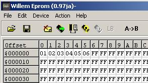
See above picture.
I entered 6 data in buffer, address from 0000 to 0005.
In this buffer, data at address 0, 2, 4 will be low byte and data at 1,3,5 will be high byte data.
The low byte data are: 01 03 05
The high byte data are: 02 04 06
When software writting, it will write one byte each time from 0000 to 0005 address. Basically this is not importand at all. You do not need to know how the software and programmer do the job.
More important, you need to know the hi, low byte position in the software buffer. And the data in buffer will be same as the data in the EPROM after a write complete.
If you want to swap the hi-low order, just click on A->B button, the software will do it for you. |
 |
|
| Reply #2
kinglyone

3 Posts |
 Posted - 10/19/2008 : 15:24:08 Posted - 10/19/2008 : 15:24:08

|
i knew there wasnt a problem with my hardware or my software. not even 3 seconds ago i was staring at the circuit diagram for the adapter and i noticed the chip's A0 line was connected to the A1 bus line on the adapter. i was just about to test my 'theory' when i logged on here. your reply confirms my theory lol...
btw, i feel kinda dumb now. some kind of documentation should be included with the adapter for 16bit programming. |
 |
|
| |
 Topic Topic  |
|
|
|

