| Author | 
                
                  Topic   | 
                  | 
              
              
                | 
                 eliotroyano 


                27 Posts  | 


                       Posted - 02/07/2010 :  16:03:51
                        
                      
  | 
                     
                    
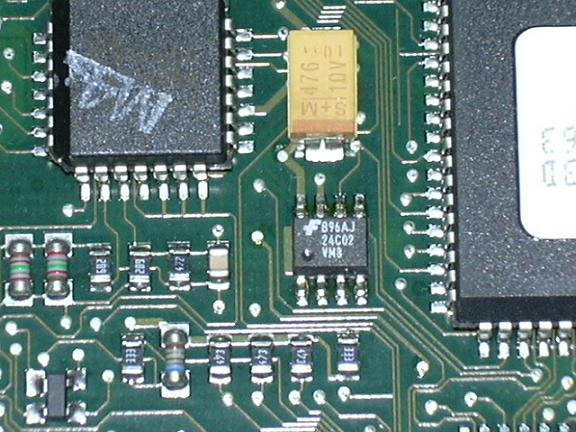
                       Hi friends. I am testing a Pomona SOIC8 testclip try to read a 24C02 chip of a Bosch ECU. You can see it here:
  Image Insert:
    106.44 KB
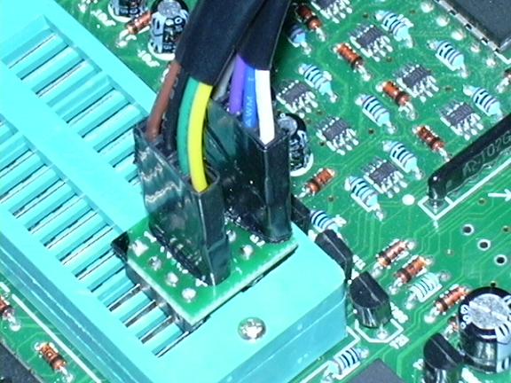
  I prepare the cable and check all the connections and are ok.
  Image Insert:
    105.94 KB
  Image Insert:
    124.09 KB
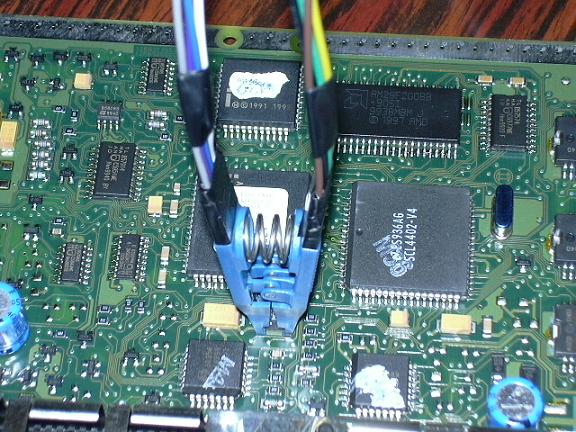
  But the GQ-3X tells me after select a 24C02 Generic Device that ID function is not available. And I try to read the chip and the GQ-3X system halts totally like it was trying to read the device but never reach it.
  I read sometimes that ICSP does not work all the times and needs to be tested. But my question is how do I know if that ECU does not allow me to try to read the device ICSP? or if I have something wrong in my cable connections? I check continuity of the testclip cable and everything is ok.
  Some advice is welcome.
  Thanks, | 
                     
                    
                       Edited by - eliotroyano on 02/07/2010  16:23:41
                     |  
                   
                 | 
              
              
                | Reply #1
                 eliotroyano 


                27 Posts  | 


                       Posted - 02/08/2010 :  11:21:52
                        
                      
  | 
                     
                    
                      |  Any comments friends??? | 
                     
                    
                        | 
                     
                   
                 | 
              
              
                | Reply #2
                 ZLM 


                2947 Posts  | 


                       Posted - 02/08/2010 :  11:28:09
                        
                      
  | 
                     
                    
                       First off all, your connection neems correct.
  But the problem is the power.  | 
                     
                    
                        | 
                     
                   
                 | 
              
              
                | Reply #3
                 eliotroyano 


                27 Posts  | 


                       Posted - 02/10/2010 :  13:18:37
                        
                      
  | 
                     
                    
                       quote: Originally posted by ZLM
  First off all, your connection neems correct. But the problem is the power. 
 
  
  Do you think that I will need an external power supply??? I notice that the Red & Green leds stays on, but the Yellow remains off. | 
                     
                    
                        | 
                     
                   
                 | 
              
              
                | Reply #4
                 ZLM 


                2947 Posts  | 


                       Posted - 02/10/2010 :  18:00:11
                        
                      
  | 
                     
                    
                       Not for programmer. The programmer only can provide power for chip itself, not for your whole model board. Your model board need need to be powered up. And only connect the pin 4, 5, 6.
  And check the pin 1,2,3 are in low(0V). Those are device address pins. 
  | 
                     
                    
                        | 
                     
                   
                 | 
              
              
                | Reply #5
                 eliotroyano 


                27 Posts  | 


                       Posted - 02/10/2010 :  18:56:42
                        
                      
  | 
                     
                    
                       quote: Originally posted by ZLM
  Not for programmer. The programmer only can provide power for chip itself, not for your whole model board. Your model board need need to be powered up. And only connect the pin 4, 5, 6.
  And check the pin 1,2,3 are in low(0V). Those are device address pins. 


  Ok I will try it and let you know. Thanks a lot. | 
                     
                    
                        | 
                     
                   
                 | 
              
              
                | Reply #6
                 eliotroyano 


                27 Posts  | 


                       Posted - 02/11/2010 :  09:42:57
                        
                      
  | 
                     
                    
                       quote: Originally posted by ZLM
  Not for programmer. The programmer only can provide power for chip itself, not for your whole model board. Your model board need need to be powered up. And only connect the pin 4, 5, 6. And check the pin 1,2,3 are in low(0V). Those are device address pins.
 
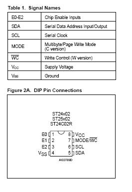
   But ZLM I have a doubt about the 24C02 pinout.
  Image Insert:
    17.6 KB
  When you mention "check pins 1,2,3 are low (0V)" you mean to force it to ground? or to just to see if all are in logical 0V, I mean the board not requesting info to 24C02? You tell me to leave pins 4(Vss),5(SDA),6(SCL) of the testclip connected and the board powered up but what about pin 7(Mode/WC)?  Should I connect it if I will write the chip?
  Thanks again for your great support, | 
                     
                    
                       Edited by - eliotroyano on 02/11/2010  09:44:56 | 
                     
                    
                        | 
                     
                   
                 | 
              
              
                | Reply #7
                 ZLM 


                2947 Posts  | 


                       Posted - 02/11/2010 :  13:40:17
                        
                      
  | 
                     
                    
                       Just to see if pin 1,2,3 are in 0V.  (They must be 0V in order to read/write).
  Ignore the pin 7 MODE. We only use byte mode according to datasheet.
  Only connect the pin 4, 5, 6 via testclip.
  Read the chip first. | 
                     
                    
                        | 
                     
                   
                 | 
              
              
                | Reply #8
                 eliotroyano 


                27 Posts  | 


                       Posted - 02/15/2010 :  17:33:43
                        
                      
  | 
                     
                    
                       quote: Originally posted by ZLM
  Just to see if pin 1,2,3 are in 0V.  (They must be 0V in order to read/write). Ignore the pin 7 MODE. We only use byte mode according to datasheet. Only connect the pin 4, 5, 6 via testclip. Read the chip first.
 
  
  Well ZLM, I test your idea and it work quite good with one board but with another one not, and I following the same steps.   | 
                     
                    
                        | 
                     
                   
                 | 
              
              
                | Reply #9
                 ZLM 


                2947 Posts  | 


                       Posted - 02/15/2010 :  21:52:45
                        
                      
  | 
                     
                    
                       If both boards are same, then you can try to short the jumper wire. There are must be something different betwwen those board.
  | 
                     
                    
                        | 
                     
                   
                 | 
              
              
                | Reply #10
                 eliotroyano 


                27 Posts  | 


                       Posted - 02/17/2010 :  05:46:47
                        
                      
  | 
                     
                    
                       quote: Originally posted by ZLM
  If both boards are same, then you can try to short the jumper wire. There are must be something different betwwen those board.
 
  
  "Short the jumper", sorry but can you explain it a little more? Thanks again for your help.
  | 
                     
                    
                        | 
                     
                   
                 | 
              
              
                | Reply #11
                 ZLM 


                2947 Posts  | 


                       Posted - 02/17/2010 :  08:35:08
                        
                      
  | 
                     
                    
                      |  Sorry. I means try to reduce the length of jumper wire. Use shorter jumper wires to try. | 
                     
                    
                        | 
                     
                   
                 | 
              
              
                | Reply #12
                 eliotroyano 


                27 Posts  | 


                       Posted - 02/22/2010 :  10:31:56
                        
                      
  | 
                     
                    
                       quote: Originally posted by ZLM
  Sorry. I means try to reduce the length of jumper wire. Use shorter jumper wires to try.
 
   ZLM finally I need to desoldered the chip because the testclip was working with one board but not with the other one. Also I notice some differences between the readings with the testclip and without it, then finally I prefer to desolder it and take that reading as good one. Thanks, | 
                     
                    
                        | 
                     
                   
                 | 
              
              
                |   | 
                
                  Topic   | 
                  |