| Author |
 Topic Topic  |
|
|
milsnips

Australia
4 Posts |
 Posted - 03/19/2015 : 15:13:40 Posted - 03/19/2015 : 15:13:40

|
hi there, im having a few issues trying to figure out how to connect up the pins between the two.
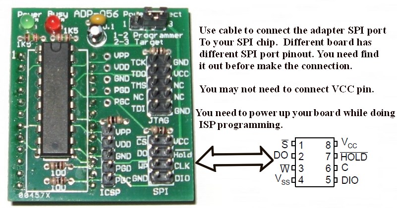
Have this ADP-056 adapter with the following SPI pin layouts:
h**p://www.c-u-s.co.uk/image/cache/data/Programmer%20adapters/JTAG_ISP_ADAPTER-700x700.jpg
the MSI motherboard however doesnt have the pins labelled and the user manual isnt much help either just says its a service interface and thats about it, no schema diagram.
any help appreciated in mapping the pins between the two.
thanks. |
|
| Reply #1
ZLM
    
2945 Posts |
 Posted - 03/20/2015 : 21:43:20 Posted - 03/20/2015 : 21:43:20

|
Image Insert:

107.42 KB |
 |
|
| Reply #2
milsnips

Australia
4 Posts |
 Posted - 03/21/2015 : 16:37:22 Posted - 03/21/2015 : 16:37:22

|
| Thanks for your reply. i got the correct pin schema from MSI and have connected it all up. By powering up the board are you saying i need to connect it up to a PSU? i thought the programmer passes in the required 3~v to power up the chip during the read/write? |
 |
|
| Reply #3
ZLM
    
2945 Posts |
 Posted - 03/21/2015 : 19:16:08 Posted - 03/21/2015 : 19:16:08

|
| The programmer is able to power up the single chip. But your chip is connected to your chip is on the motherboard and programmer is not able to power up your motherboard. |
 |
|
| Reply #4
milsnips

Australia
4 Posts |
 Posted - 03/22/2015 : 01:55:17 Posted - 03/22/2015 : 01:55:17

|
i got in touch with MSI support re:the pin mapping and they sent me this:
so i connected up the pins accordingly, and because is uses VCC i switched the power mode to 1-2 (programmer) to supply the 3.6 or so vaults required for the Winbond BIOS chip.
I cant read all the numbers on the chip due to obstructed view but says WinBond W25Q64... so i selected that in device list, and also tried the other one also. Device id always returns 000000. tried doing a write anyway which took about 10 or so minutes, then after that it tries to verify and also returns the device id failed 000000 message.
Are you saying, alongside the connected VCC cable which provides the 3.6v to the chip, i also need to power up the motherboard with the PSU cable in order to read/write to the chip?
|
Edited by - milsnips on 03/22/2015 01:58:50 |
 |
|
| Reply #5
ZLM
    
2945 Posts |
 Posted - 03/24/2015 : 16:52:28 Posted - 03/24/2015 : 16:52:28

|
The picture you got from MSI is the connection between you chip and its on board SPI port.
If you can find this port on your motherboard, then you can connect the SPI port to the programmer adapter SPI port.
You need to power up the motherboard.
If it still does not ork, you need to remove the chip from the board and program it on th programmer.
That will 100% work. |
 |
|
| Reply #6
milsnips

Australia
4 Posts |
 Posted - 03/25/2015 : 02:25:06 Posted - 03/25/2015 : 02:25:06

|
Thanks for your reply. I'm still having no luck with it, this is how i've set it up.
1. ADP-056 connected to the MSI board pins, as per schema
2. additional powersupply from 2nd pc connected to the msi board 24 pin power slot (24pin JPWR1)
3. set the power mode on ADP-056 to 2-3 (TARGET)
When i press the power button on the board, it powers up for maybe 1/4second then a DRMOS ALARM led lights up (meaning problem with bios) and it powers down straight away and just repeats that in a loop every few seconds until i cut the power. Because it does this i dont think i can provide a consistant supply of power to the board, is that correct?
Few other points... when i click "Id" to identify the chip (after selecting WinBond w25Q64) it returns FFFFFF, Not in library unknown device, another time it said Id 000000 when the motherboard is powered, and then another time (i think when i took out the jumper pin from the power select, it returned 000027 Mostek which was strange.
Board has 2 chips both are soldered on and in difficult area to desolder as they are partially under a heatsink
MSI replied to me saying the model number of the winbond chips are W25Q64CVSSIG or W25Q64FVSSIG. can you confirm if the programmer supports these?
UPDATE:
-------
Looks like there is an issue with keeping my moatherboard powered up to be able to read the chip properly. because it only stays on for 1/4second, in that time if i press "ID" it can identify the chip correctly but the power doesnt stay on long enough to try and read/rwite. not sure what to do with this one...
|
Edited by - milsnips on 03/26/2015 01:22:52 |
 |
|
| Reply #7
ZLM
    
2945 Posts |
 Posted - 03/28/2015 : 13:15:45 Posted - 03/28/2015 : 13:15:45

|
The W25Q64CVSSIG or W25Q64FVSSIG are supported, no problem.
I am still thinking the problem is the power issue. The chip need power during the reading and writting.
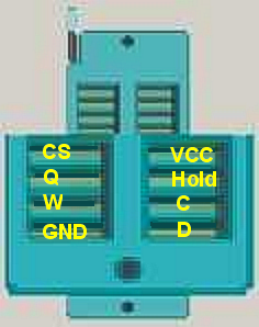
You may try direct connect between ZIF socket and your chip.
See:
Image Insert:

124.39 KB |
 |
|
| Reply #8
anniel
    
2576 Posts |
 Posted - 02/23/2018 : 11:15:01 Posted - 02/23/2018 : 11:15:01

|
quote:
Originally posted by milsnips
Thanks for your reply. I'm still having no luck with it, this is how i've set it up.
1. ADP-056 connected to the MSI board pins, as per schema
2. additional powersupply from 2nd pc connected to the msi board 24 pin power slot (24pin JPWR1)
3. set the power mode on ADP-056 to 2-3 (TARGET)
When i press the power button on the board, it powers up for maybe 1/4second then a DRMOS ALARM led lights up (meaning problem with bios) and it powers down straight away and just repeats that in a loop every few seconds until i cut the power. Because it does this i dont think i can provide a consistant supply of power to the board, is that correct?
Few other points... when i click "Id" to identify the chip (after selecting WinBond w25Q64) it returns FFFFFF, Not in library unknown device, another time it said Id 000000 when the motherboard is powered, and then another time (i think when i took out the jumper pin from the power select, it returned 000027 Mostek which was strange.
Board has 2 chips both are soldered on and in difficult area to desolder as they are partially under a heatsink
MSI replied to me saying the model number of the winbond chips are W25Q64CVSSIG or W25Q64FVSSIG. can you confirm if the programmer supports these?
UPDATE:
-------
Looks like there is an issue with keeping my moatherboard powered up to be able to read the chip properly. because it only stays on for 1/4second, in that time if i press "ID" it can identify the chip correctly but the power doesnt stay on long enough to try and read/rwite. not sure what to do with this one...
For those in a similar situation you simply need to jump the green wire of the 20 or 24 pins connector to any black wire to keep the power supply running. |
 |
|
| |
 Topic Topic  |
|

